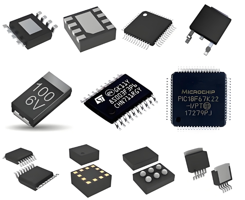
**Designing a 4 GHz Phase-Locked Loop (PLL) Frequency Synthesizer with the ADF4360-2BCP**
The demand for stable, high-frequency local oscillator (LO) signals is paramount in modern RF systems, from wireless infrastructure to test and measurement equipment. Designing a Phase-Locked Loop (PLL) frequency synthesizer to generate a precise 4 GHz signal presents significant challenges in phase noise, spurious performance, and loop stability. The **ADF4360-2BCP**, a highly integrated integer-N synthesizer and voltage-controlled oscillator (VCO) from Analog Devices, provides a robust foundation for such a design.
**Core Architecture and Component Selection**
The ADF4360-2BCP integrates the key components of a PLL synthesizer onto a single chip: a **programmable PLL core**, a **fundamental VCO** with a center frequency of 3.8 GHz, and a **differential output buffer**. The VCO tuning range (3475 MHz to 4025 MHz) comfortably encompasses the 4 GHz target, making it an ideal choice. The design's external components are critical to performance. A high-stability, low-phase-noise **crystal reference oscillator** (e.g., 10 MHz or 20 MHz) is essential, as its noise directly impacts the in-band phase noise of the synthesizer. The **loop filter**, a passive RC network external to the IC, is arguably the most crucial part of the design. It must be carefully calculated to achieve a balance between **lock time**, **phase noise**, and **reference spur suppression**.
**Design Procedure and Calculations**
1. **Setting the Frequency:** The output frequency (RFout) is set by the formula: RFout = [P × (INT + (FRAC / MOD))] × (Fref / R). For integer-N mode (FRAC=0), this simplifies to RFout = (P × INT × Fref) / R. The on-chip prescaler (P) is fixed at 8/9 for this family. Selecting a reference frequency (Fref) of 10 MHz and a reference divider (R) of 1, the integer value (INT) is calculated as INT = (RFout × R) / (P × Fref) = (4000 × 1) / (8 × 10) = 50.
2. **Designing the Loop Filter:** The loop filter's components (resistors and capacitors) are determined by the desired **loop bandwidth** and phase margin. A bandwidth of approximately 1/10th to 1/20th of the reference frequency (e.g., 10 kHz to 50 kHz for a 10 MHz reference) is a common starting point. Using Analog Devices' ADIsimPLL design tool or standard PLL equations, values for the charge pump current, loop filter order, and components can be optimized. A second or third-order passive filter is typical, designed to provide sufficient phase margin (> 45°) for stability while attenuating reference spurs.
3. **PCB Layout Considerations:** RF PCB layout is non-negotiable for success at 4 GHz. A solid, continuous ground plane is mandatory. The **VCO supply line must be heavily decoupled** with a combination of ferrite beads and capacitors to prevent noise from coupling into the highly sensitive VCO core. The differential RF outputs (RFoutA and RFoutB) should be routed symmetrically and connected to the load (e.g., a mixer or amplifier) with controlled-impedance transmission lines, preferably **coplanar waveguide (CPW)** or microstrip.

**Performance Optimization and Challenges**
Achieving low phase noise requires minimizing the noise contributions from all sources: the reference oscillator, the PLL's phase frequency detector (PFD) and charge pump, the integer-N divider, and the VCO itself. While the integer-N architecture is simpler than fractional-N, it necessitates a lower PFD frequency for a given channel step, which can compromise phase noise and lock time. The primary challenge is mitigating **reference spurs** caused by the periodic correction pulses from the charge pump. The loop filter must be designed to provide adequate attenuation at the reference frequency offset (10 MHz in this case). Furthermore, proper shielding and isolation of the synthesizer from noisy digital sections of the board are essential to prevent unwanted coupling and degradation of spectral purity.
**ICGOODFIND**
The ADF4360-2BCP offers a highly integrated and effective solution for generating 4 GHz signals, simplifying design complexity and reducing board space. A successful implementation hinges on meticulous attention to three external elements: a clean reference clock, a meticulously calculated loop filter for stability and spur rejection, and an RF-optimized PCB layout with impeccable power supply decoupling. This combination allows designers to leverage the integrated VCO's performance fully, creating a compact and reliable frequency source for demanding 4 GHz applications.
**Keywords:**
1. **Phase-Locked Loop (PLL)**
2. **Voltage-Controlled Oscillator (VCO)**
3. **Loop Filter**
4. **Phase Noise**
5. **Reference Spurs**
